By Matt Lemieux, The NEBB Professional – Q2 2024 Edition
Biological safety cabinets (BSCs) are ubiquitous in laboratories, cleanrooms, and many other research and production venues. BSCs are utilized as primary engineering controls (PEC). They are distinct from fume hoods and likewise from unidirectional (laminar) flow benches, and are tragically, all too often, mistaken as such by facilities planners, engineers, and end-users. Biological safety cabinets, designated as Class II by the regulatory standard, NSF/ANSI 49, differ from other primary engineering controls in that they provide three kinds of protection: (1) The personnel protection offered by a chemical fume hood, (2) the sterile work area provided by the unidirectional HEPA flow bench, providing product protection, and (3) the environmental protection offered by the HEPA filtered BSC airflow exhaust pathway.
This complex, integrated engineered control is accomplished by clever design of the cabinet’s internal plenums, work surfaces, discharge plenums, and ducted connections to building exhaust systems. Work surfaces are exposed strictly to HEPA-filtered sterile air and personnel work access openings are subject only to protective ambient room inflow velocities. These two airstreams only mix beyond the critical work areas in the cabinet’s rear negative pressure plenum and a portion of the internal cabinet blower air–equivalent to the work access opening inflow for Type A cabinets–is exhaust through the cabinet’s exhaust HEPA filter. BSCs are fixed sash height devices (unlike fumehoods), although they are equipped with slidable or hinged windows for product insertion, removal, and cleaning. When in operation and product manipulations are taking place, the hood sash is at a predetermined fixed elevation.
As a rule, Class II BSCs can be either self-contained and free-standing in the laboratory (Type A) or connected to building exhaust systems (Type B). A variation of type A can also connect to the building exhaust system – these are nominated as Class II, Type A2-vented. These BSCs were formerly designated as Class II Type A/B3. In this arrangement, the cabinet’s internal HEPA-filtered exhaust discharges to a remote exhaust fan to provide additional environmental protection. The reason for opting for this installation configuration is because HEPA filters are limited in their filtering efficiency to discrete particulate matter, this building-connected installation is appropriate when volatile hazards or radioisotopes are used in small quantities as part of the product manipulations. Common applications for the Class II A2 Vented cabinets include isoflurane used for anesthetizing animals, volatile chemotherapeutic agents, combustion products, and small amounts of radioisotope vapors.
Figure 1 illustrates the airflow patterns inside a Class II Type A2-Vented BSC in an elevation cross-section.
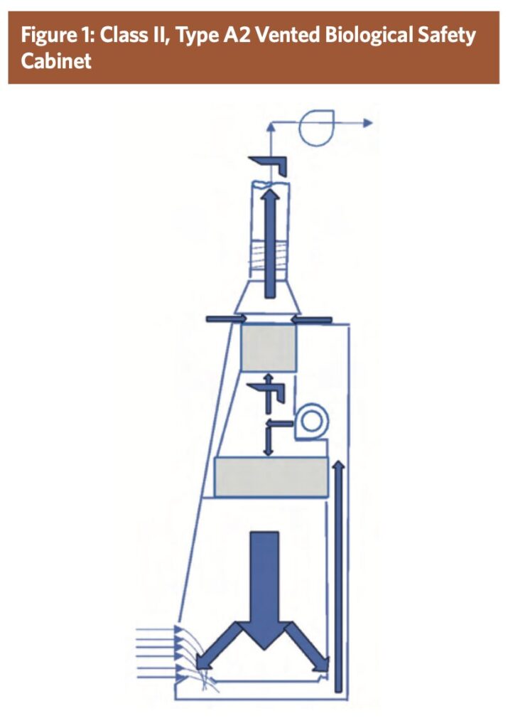
With this design, the work access opening air quantity is discharged out through the exhaust HEPA where it joins with bypass room air to comprise the remote exhaust fan air quantity. A recirculation loop of HEPA-filtered air contained in the cabinet provides the sterile work surface conditions. The bypass air is normally induced into the canopy exhaust duct downstream of the cabinet exhaust and below the finished ceiling of the room. Class II Type A cabinets are colloquially known as 70/30 cabinets, meaning 30% of the cabinet internal blower is induced and exhausted. However, newer cabinets are designed with less HEPA-filtered recirculation air and are closer to 50/50.
Equation 1 describes the airflow quantities for a canopy-connected Class II A2 – vented cabinet installation.
Equation 1:
QT = QI + QB
Where:
QT is the total cfm in the duct riser from the BSC.
QI is the work access opening cfm.
QB is the bypass cfm.
Current Problems
Accredited certifiers perform mandatory, routine certification on these cabinets. Among other tests, both HEPA filters must be integrity-tested with a handheld scanning probe and the work access opening inflow velocity must be verified within a stringent ±5 % of design. Additionally, with each certification cycle, the field certifier must verify the canopy airflow alarm system operation by manually blocking the canopy exhaust airflow. NSF/ANSI 49 Normative annex N.5 specifies the requirements for routine field certification, stating: Containment loss of canopy connection on Type A1 or A2 cabinets – shall be tested at the time of alarm verification – introduce a visible medium source into the canopy air intake(s) while slowly reducing the exhaust volume until there is a loss of capture of the visible medium into the canopy air intake(s). The audible and visual canopy alarms shall respond within 15 seconds…
Unfortunately for the field technician, there is frequently no installed provision for reducing the exhaust volume, as airflow dampers are a suggested installation feature. However, they are not mandated. The standard obliges the certifier to perform this test but often there is no adjustment provided to accomplish this. There may be a manual balancing damper above the secure finished ceiling or there may be a branch automatic valve under the authority of the facilities staff or third-party controls contractor. Decreasing the common fan speed is not a viable option, as it will cause all the other BSCs on this system to simultaneously alarm.
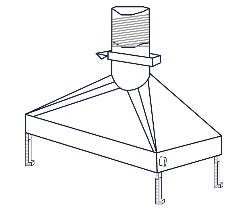
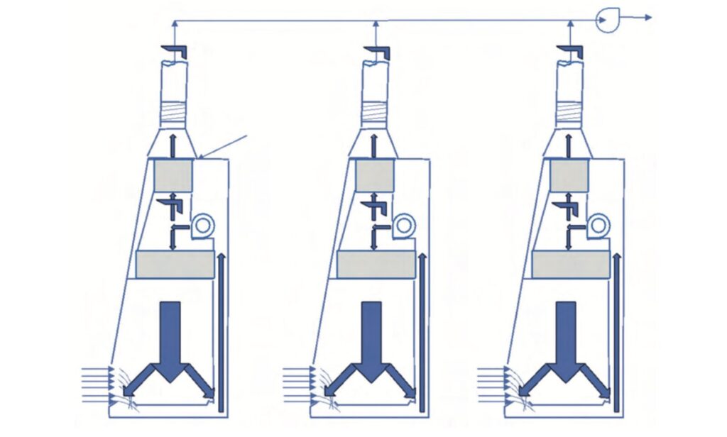
In the early days of laboratory design, these building-connected BSCs were directly coupled to 8”, 10”, or 12” galvanized ductwork – balanced to exhaust an air quantity equal to the work access opening inflow. This raised an issue with certification setpoints where-by if the exhaust system fluctuated or more likely, if there were multiple cabinets connected to a single remote blower, a change in one affected the others. So, if an operator shut off the cabinet blower or closed the window sash on one cabinet, as shown in Figure 2, the other connected hoods would inadvertently go out of certification tolerance. This recognized shortcoming led to a more enlightened design (as shown in Figure 1), whereby bypass air canopies are utilized so that ideally, the work access opening inflow velocity of associated cabinets would not modulate as one or more cabinets were modified. System variations would be absorbed by the canopy bypass air instead and the work access opening airflows would remain constant. On April 15th, 2016, the regulatory body, NSF/ANSI 49, issued a memorandum reading, “NSF Accredited field certifiers shall no longer certify either direct-connected Type A cabinets or canopy-connected Type A cabinets without alarms, even if specifically asked to do so by the customer.”
Figure 2 Shows the original configuration of multiple directly connected A2 vented cabinets. Canopy duct connections were thus required on Class II, A2 Vented biological safety cabinets going forward. Prescribing this engineering solution to the problem, however, raises other collateral issues. The first issue is how much bypass air to exhaust. Further, how can the cabinet exhaust filter air, QI, be integrity tested for downstream challenge concentration when it is being diluted by the inrush of dilution room bypass air? How can the exhaust HEPA filter be integrity tested using a hand-held scanning probe without adequate access for the hand and arm of the technician? How can the work access opening airflow be measured in the duct if it is conjoined with the room bypass air? How is the duct pressure in the canopy transition regulated with widely varying exhaust and bypass air? Finally, how can the exhaust filter downstream surface be sealed with tape and plastic during planned biological decontamination efforts without adequate technician access openings and with the disruptive suction pressure and sideways turbulence caused by the canopy bypass?
Previously, when the cabinets were directly connected as in Figure 2, these incipient issues were preempted by optionally performing overall penetration testing (rather than scanning) of the exhaust filter, pitot-traversing the exhaust duct, and closing an airtight duct damper. NSF/ANSI 49 makes various suggestions for canopy installation including typical canopy connection duct pressures, flexible duct sections and accessible manual balancing dampers but does not, nor cannot, mandate these suggestions. The particular site configuration is subject to the whims of the design engineer and site installation contractor.
In a recent case study, we encountered a Q.A. laboratory having four of these Class II, Type A2 Vented cabinets sharing a common exhaust blower and having four dedicated, adjustable CAV automatic air valves. When the branches were each balanced for the appropriate bypass CFM, the excess duct static pressure inside the BSC manufacturer-supplied canopy transitions was so high (negative) that it caused the cabinet ECM blower wheels to rotate backwards, and the motors did not have sufficient torque to overcome this imposition. Consequently, each time the cabinet blower switches were energized, after a few seconds, a blower failure alarm was indicated – preventing use of the cabinets.
Figure 2: Direct connected A2 cabinets with common exhaust system
Quite frequently it is impractical to perform a confident exhaust HEPA filter integrity scan on the downstream side of the exhaust filter due to the turbulent dilution of the inrushing bypass air. It is also incredibly challenging to seal the exhaust HEPA filter with tape and plastic when performing a decontamination without adequate work opening space and the ever-present danger of unintentionally sucking the 4 ft² sheet of plastic up through the exhaust duct.
In summary, NSF/ANSI 49 does require canopy connections on the Class II Type A2 vented cabinet installations. It also requires audible and visual alarms to indicate loss of capture of the exhaust HEPA filtered air, QI. Furthermore, the regulation requires that the field certifier routinely validates the operation of the loss of capture alarm by restricting the total exhaust duct air, QT. The regulation also prescribes that the exhaust HEPA filter be integrity tested at each certification. The standard also mandates that the exhaust HEPA filter be sealed airtight when the BSC is undergoing decontamination procedures. However, NSF/ANSI 49 limits its authority to the design, construction, performance, and certification of Class II cabinets. It can only inform and suggest critical aspects of the client site applications.
Therefore, what exactly is an HVAC duct canopy?
NSF/ANSI–49 is parsimonious in its requirements for a canopy. A canopy is “A BSC exhaust connection where there are one or more openings or gaps in the connection between the BSC and the external exhaust system.” NSF/ANSI 49 also distinguishes between a canopy and a modified canopy installation as, “Installation of any canopy other than a designated acceptable option for an NSF-listed biosafety cabinet.” NSF/ANSI 49 provides an informative annex discussing the canopy transition in which it indicates, “This pressure should typically be 0.001 to 0.01 in w.g. at the canopy’s connection to the exhaust system, depending on the canopy design, BSC exhaust volume, and possible obstructions around the canopy’s openings.” Furthermore, NSF/ANSI 49 describes the canopy accordingly, “In normal operation, the volume of room air drawn into the canopy connection’s openings, gaps, or both, shall be sufficient to ensure the capture of all of the BSC’s HEPA filtered exhaust, as verified by a visible medium.” Another prescription reads, “The flow of room air into the canopy connection through openings, gaps, or both provides assurance of consistent BSC performance during fluctuations in exhaust system flow rate, room pressure, or both.” Finally, the canopy must be designed such that, “The measured (work access opening inflow velocity, VI) shall be no more than 8 ft per minute below the lowest value of inflow velocity range stated on the cabinet data plate…” when the facility exhaust system is blocked. Elsewhere, “Inflow velocity shall not be reduced by more than 10 feet per minute after turning off the facility exhaust.” NSF/ANSI 49 provides a guideline for QT in its Informative appendix table I.1.1 as, “If canopy connected, typically 100 CFM/ft of BSC width or less.” This guidance value is evaluated for adequacy herein. We will examine the above guideline to see if it satisfies all the engineering design constraints of canopy connections.
NSF/ANSI 49 utilizes the phrase “properly designed canopy connection” and it is this very concept that we will explore.
The canopy concept for Class II A2 hoods intended to be building-connected was originally referred to as a thimble connection or a loose-duct connection. With the development of more enlightened laboratory engineering, the term canopy came to be used to represent this type of installation. The word canopy has an interesting etymology. It comes from the ancient Greek root word, kανοπσ − /’kanəps’/, meaning mosquito. The Greek noun kανοπε, pronounced canopy, came to mean mosquito bed netting. The American Institute of Architects defines a canopy as “an overhead roof or structure over which fabric or metal cover is attached able to provide shelter.” A canopy is distinct from an awning, which is a cantilevered cover attached to the building, because the canopy can be suspended or free
standing.
Figure 3 illustrates a canopy connection as envisioned by the Industrial Ventilation Handbook.1
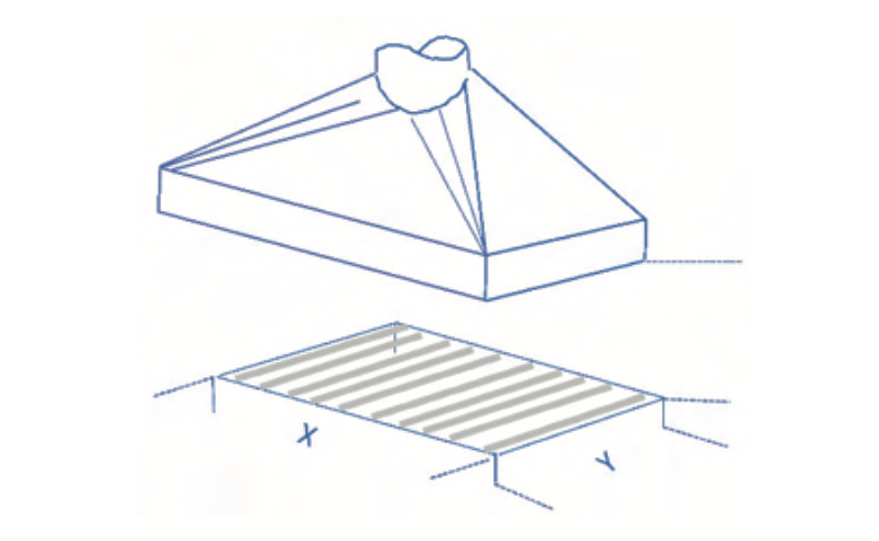
With this nomenclature, Equation 2 gives the total perimeter, P, and Equation 3 yields the cross-sectional bypass area, AB. X and Y are the nominal dimensions of the exhaust HEPA filter.
Equation 2:
P = 2 * x + 2 * y
Equation 3:
Figure 3: Canopy Connection
AB = P * D
Equation 4 gives the bypass CFM (QB) as a function of area and velocity, VB, where KV is an empirical, dimensionless correction factor.
Equation 4:
QB = AB * VB * KV
Our internal laboratory research at VTG, LLC. characterizes the variation (loss of constancy) of work access opening inflow, QI, at various canopy suction pressures. Figure 4 shows the loss of constancy occurring at approximately 0.012” H2O. This value is substantially in agreement with the suggestions found in NSF/ANSI 49: This pressure should typically be 0.001 to 0.01 in w.g. at the canopy’s connection to the exhaust system.
Figure 4
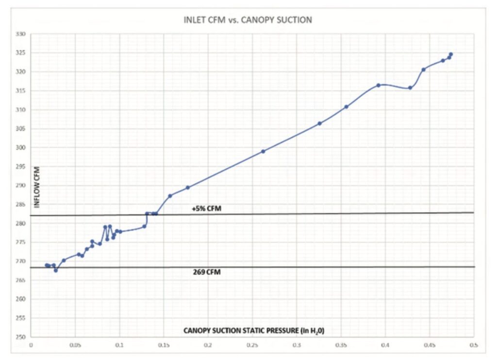
This increased exhaust airflow phenomenon occurs because by reducing the downstream static pressure on the exhaust HEPA filter, the pressure drop (Δp) increases on the exhaust HEPA filter and augments the resultant airflow.
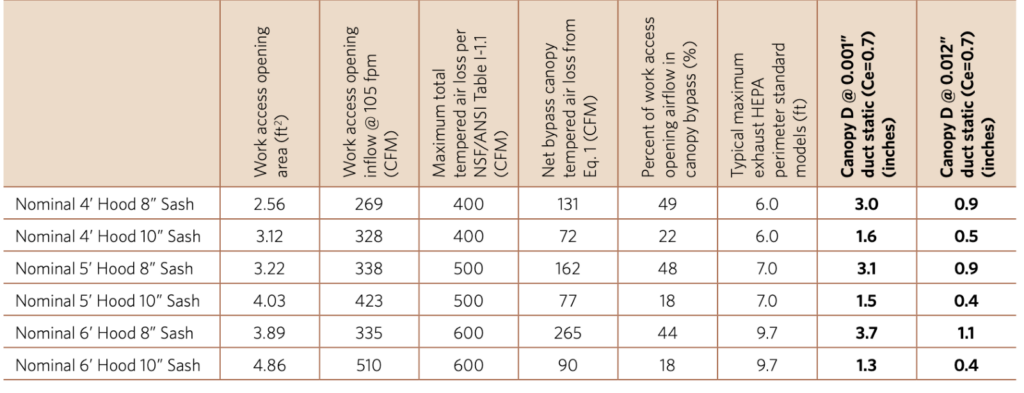
Based on the assumption that 100 CFM/ft. of cabinet width is an adequate exhaust quantity, Figure 5 tabulates the calculated canopy slot height (nominal), D, based on common exhaust filter perimeters at the minimum and maximum allowable canopy suction pressure (0.001 in H2O – 0.012 in H20) for 8-inch and 10-inch work access opening sash heights for nominal 4-, 5- and 6-foot wide BSCs. With a nominal inflow velocity work access opening of 105 fpm, this table recommends between approximately 15 – 45% bypass flow beyond the work access opening inlet flow. Each installation is going to have a maximum available branch/valve CFM to service that IIA2 Vented BSC. The net canopy bypass CFM is described by Equation 1. The work access opening CFM, QI, must be maintained ±5% during operation for the BSC to remain certified.
The table values are consistent with the NSF/ANSI 49 table I-1.1 guideline of: ≤ 100 CFM/ft. A coefficient of entry loss factor, Ce = 0.7 is assumed for conversion of suction pressure to canopy cross-section inlet velocity, VB.
The range of canopy slot access openings is between 0.4 inch and 3.7 inches. This coincides with a range of between 18 – 49% above QI. These heights are based on the nominal perimeter, PN, of the exhaust HEPA filter and, in practice, would need to be increased to accommodate the physical open perimeter of the canopy transition including the support frame, spacing or any sliding panel openings to realize the actual perimeter opening, PA.
Equation 5 describes the relationship between velocity and velocity pressure.
Equation 5: Velocity/Pressure Conversion
V = 4005 * Ce * √VP
Where:
V is velocity (fpm).
VP is velocity pressure (in H2O).
Ce is a dimensionless, empirical energy conversion loss coefficient. (0 < Ce < 1.0)
Equation 6 expands upon Equation 5 to incorporate volumetric flow, Q, and area A, under a static pressure potential.
Equation 6: Effective Leak Area
ELA = Q’B / 2610 * √SP * Ce
Where:
ELA is effective leak area (in²)
SP is static pressure potential (in H2O)
Q’B is the airflow quantity flowing out of the canopy transition into the room (CFM)
Figure 5: Canopy slot elevations (D)
Suggested Changes
The engineering design constraints for a properly designed canopy connection is summarized below:
1. Maintain cabinet bypass velocity, VB, (fpm) under normal operating conditions accordingly: 88 ≤ VB ≤ 307. This is the resultant velocity with canopy duct static pressure PC (in H2O), 0.001 ≤ PC ≤ 0012, with a Ce = 0.7, to maintain capture phenomenon.2
2. Provide, under normal operating conditions, a sufficiently large enough cross-sectional area (ELA), AB, such that in the event of exhaust failure, QI, is maintained adequately large enough to ensure that VI is not below (92 fpm). Where VI is the velocity at the work access opening.
3. Maintain consistent work access opening velocities, VI, ± 5 fpm under varying exhaust system static pressure conditions.
4. Provide an audible and visual alarm strategy which indicates both when the canopy pressure is too high (more positive) to indicate loss of capture as well as too low (more negative) to indicate loss of certification tolerance at VI.
5. Enable adequate clearance space for exhaust HEPA filter integrity testing during routine
certifications.
6. Enable the certification technician to reduce the exhaust air volume, QT, both when performing the site installation alarm verification and when performing the exhaust HEPA filter integrity testing without affecting the adjacent facility space.
7. Enable the certification technician adequate space and ability to block the exhaust suction to reliably seal the exhaust HEPA filter with tape and plastic during the decontamination process.
Our internal VTG research mentioned above, also discovered that the maximum achievable positive static pressure, downstream of the exhaust filter, in a sealed duct (simulating exhaust fan failure) was approximately 0.05” H2O produced by the internal cabinet blower. If we revisit Figure 5 with the additional condition detailed in design constraint #2 and the application of Equation 6, we produce a modified list of canopy slot heights, D as shown in Figure 6.
Figure 6: Canopy Slot Elevations (D)
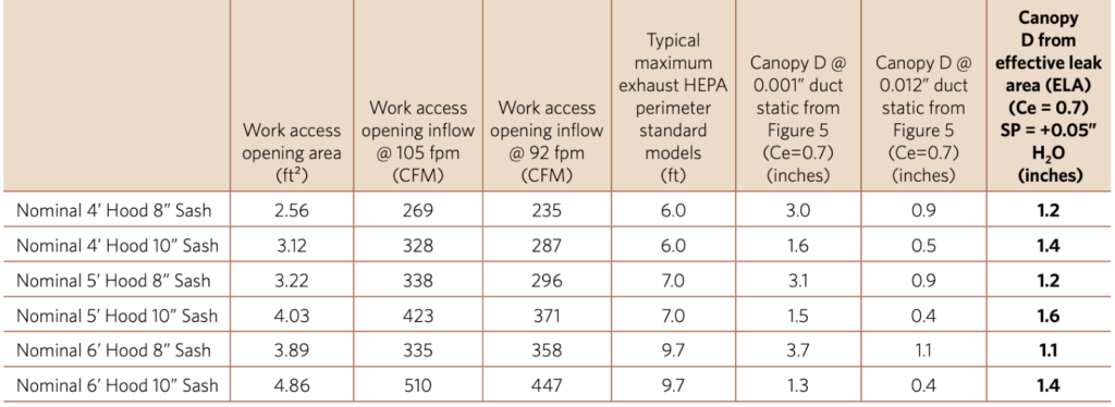
The actual canopy opening elevation, DMAX, should be taken from Figure 6. The associated QB should be sufficient to achieve at least 88 fpm inflow at DMAX.
To provide a properly designed canopy connection four modifications should be specified. (1) Provide a suspension system and/or adjustable slot to maintain the appropriate slot opening elevation, D. (2) Provide a bi-modal positioning mechanism for uplifting the canopy assembly to allow for HEPA filter integrity scanning and decontamination access. (3) Include a blast gate or other adjustable airflow damper device to allow for site installation assessment during certifications. (4) Provide an alarm system to monitor both hi-negative and low-negative (positive) pressure.
Figure 7 illustrates a suggested conceptual properly designed canopy connection.
By including a mandatory blast gate damper in the throat of the canopy round duct, two incipient issues are rectified. This allows the technician agency to verify the alarm operation without affecting other BSCs in the facility. Without the tools to do so, it is unrea sonable for NSF/ANSI 49 to mandate the alarm operation as a portion of the routine field BSC certification, burdening the certifiers with an impossible task. Incorporation of an integral blast gate, coupled with adjustable height mounts facilitates exhaust HEPA filter integrity scanning and enables decontamination sealing and taping. The installed alarm is adjusted to alarm at low pressure (highly negative, i.e., ≤ -0.012” H2O) and may incorporate a sail switch to indicate positive canopy duct pressure. At a minimum, the canopy positioning must be bimodal for normal operation and for service, certification, and maintenance. While NSF/ANSI – 49 does not have the authority to mandate such a device, it is incumbent upon the manufacturers who are already providing their own canopy designs to incorporate these suggestions.
Figure 7: Properly Designed Canopy Connection